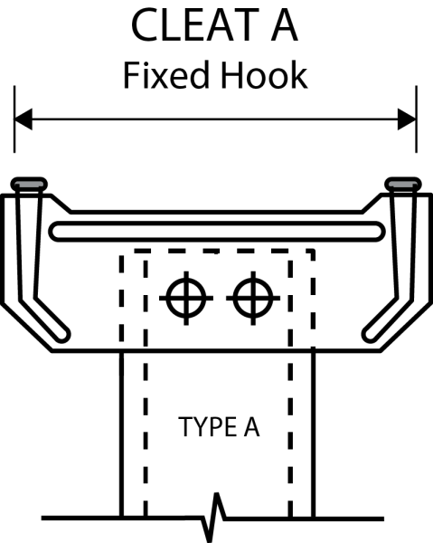
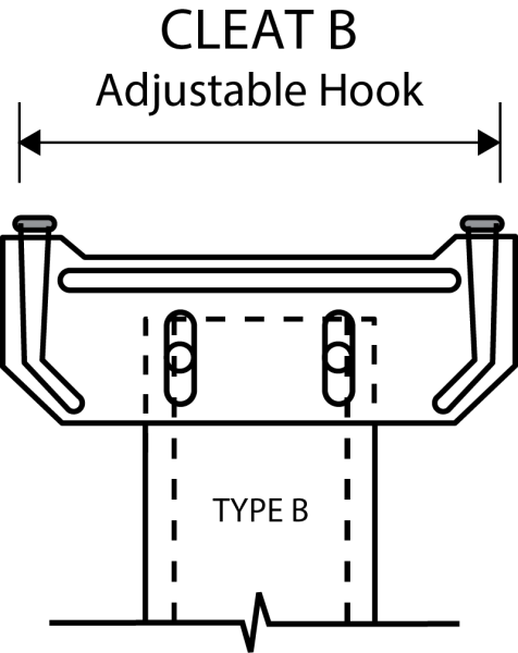
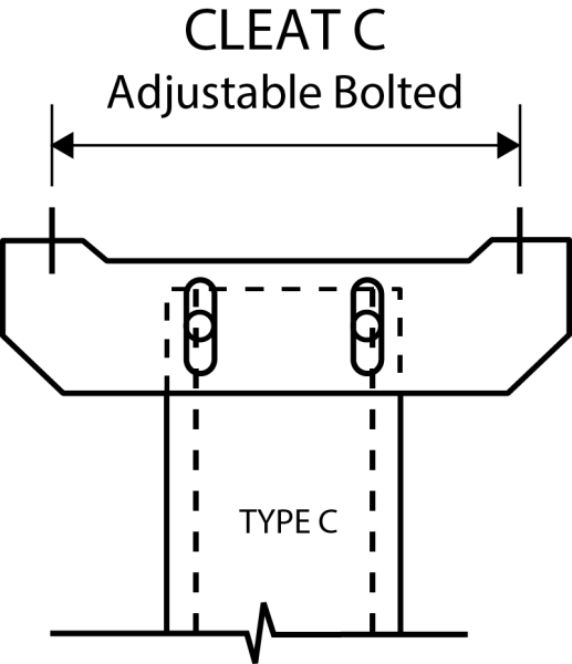
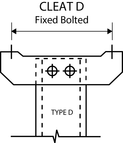
HST Bracing consist of 1 channel and 2 cleats. It is designed to fit between purlins pre-punched. The apex purlin has a bolted connection, thereafter, hook connections are used to the eaves. The eaves purlin has a bolted connection which can be supplied adjustable if required. To maintain a continuous line, the eaves and apex purlins require holes offset 25mm each side of the nominal bracing line.
Bracing length should be calculated at the purlin spacing less 2mm.
Heavier zinc coating weight of Z450 can also be provided on request, subject to minimum order quantity and lead times.
Steel Thickness, Grade, and Zinc Weight
| Steel Thickness | Grade | Zinc Weight |
|---|---|---|
| 0.95mm | G250 | 275 g/m² |
Standard Brace Channel
100 x 32 lipped channel in 0.95 thickness
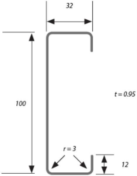
| d | b | Steel Thickness |
|---|---|---|
| 100 | 32 | 0.95 |
Bracing systems are essential to the stability and security of Structures built to withstand lateral stresses like wind, seismic activity, and other loads that could cause the structure to sway or collapse.
All HST brace channels are manufactured with cleats custom fitted to suit the purlin size and spacing.
Cleats information


| Purlin Size | x | y |
|---|---|---|
| 150 | 80 | 80 |
| 200 | 120 | 120 |
| 250 | 160 | 160 |
| 300 | 200 | 200 |
| 350 | - | 240 |
| 400 | - | 280 |
| Holes | Cleat A | Cleat B | Cleat C | Cleat D |
|---|---|---|---|---|
| Ø18 | Ø18 | Ø14 / Ø18 / Slotted | Ø14 / Ø18 / Slotted |
Sectional Properties
| purlin size | Area | WEIGHT | SECOND MOMENT OF AREA (GROSS SECTION) | SECTION MODULUS | RADIUS OF GYRATION | TORSION CONSTANT | WARPING FACTOR | |||
|---|---|---|---|---|---|---|---|---|---|---|
| As | Wt | Ix | Iy | Zx | Zy | rx | ry | J | Iw | |
| HST | mm2 | KN/M | 10⁶MM⁴ | 10⁶MM⁴ | 10ᶟMMᶟ | 10ᶟMMᶟ | MM | MM | MM⁴ | 10⁹MM⁶ |
| 100/12 | 253 | 0.019 | 0.423 | 0.092 | 8.38 | 2.78 | 40.9 | 19.1 | 111 | 0.21 |
| 100/15 | 316 | 0.024 | 0.525 | 0.114 | 10.45 | 3.44 | 40.8 | 18.9 | 222 | 0.26 |
| 100/19 | 400 | 0.031 | 0.658 | 0.141 | 13.14 | 4.29 | 40.6 | 18.7 | 456 | 0.31 |
| 150/12 | 386 | 0.030 | 1.38 | 0.249 | 18.1 | 6.14 | 59.8 | 25.4 | 170 | 1.54 |
| 150/15 | 483 | 0.037 | 1.72 | 0.308 | 22.6 | 7.61 | 59.7 | 25.2 | 338 | 1.87 |
| 150/18 | 578 | 0.044 | 2.05 | 0.364 | 27.0 | 9.01 | 59.6 | 25.1 | 590 | 2.19 |
| 200/12 | 478 | 0.037 | 3.00 | 0.392 | 29.6 | 8.04 | 79.2 | 28.6 | 211 | 3.93 |
| 200/15 | 598 | 0.046 | 3.75 | 0.486 | 36.9 | 9.98 | 79.2 | 28.5 | 419 | 4.83 |
| 200/18 | 717 | 0.055 | 4.48 | 0.577 | 44.2 | 11.90 | 79.1 | 28.4 | 732 | 5.67 |
| 250/13 | 625 | 0.048 | 5.85 | 0.655 | 46.8 | 11.90 | 96.8 | 32.4 | 325 | 10.4 |
| 250/15 | 722 | 0.056 | 6.76 | 0.753 | 54.0 | 13.7 | 96.7 | 32.3 | 506 | 11.9 |
| 250/18 | 866 | 0.067 | 8.09 | 0.897 | 64.7 | 16.3 | 96.6 | 32.2 | 885 | 14.0 |
| 300/15 | 847 | 0.065 | 11.5 | 1.23 | 76.4 | 18.5 | 116 | 38.1 | 594 | 26.4 |
| 300/18 | 1018 | 0.078 | 13.7 | 1.46 | 91.6 | 22 | 116 | 37.9 | 1039 | 31.2 |
| 300/24 | 1382 | 0.106 | 18.6 | 1.95 | 124 | 29.5 | 116 | 37.6 | 2653 | 41.1 |
| 300/30 | 1711 | 0.132 | 22.9 | 2.38 | 153 | 36.0 | 116 | 37.3 | 5134 | 49.4 |
| 350/18 | 1123 | 0.086 | 20.1 | 1.63 | 115 | 24 | 134 | 38.1 | 1146 | 46.7 |
| 350/24 | 1526 | 0.117 | 27.2 | 2.17 | 155 | 32.1 | 133 | 37.7 | 2930 | 61.6 |
| 350/30 | 1891 | 0.146 | 33.5 | 2.65 | 192 | 39.3 | 133 | 37.4 | 5674 | 74.3 |
| 400/20 | 1365 | 0.105 | 31.1 | 1.97 | 155 | 28.6 | 151 | 38.0 | 1730 | 73.1 |
| 400/24 | 1670 | 0.128 | 37.9 | 2.39 | 190 | 34.7 | 151 | 37.8 | 3206 | 87.7 |
| 400/30 | 2071 | 0.159 | 46.9 | 2.92 | 234 | 42.5 | 150 | 37.5 | 6214 | 106 |
Note: All section properties are for the gross section.
Section capacities
| purlin size | SECTION MOMENT CAPACITY | DISTORTIONAL BUCKLING MOMENT CAPACITY | FLEXI-TORSIONAL BUCKLING MOMENT CAPACITY φbmfbx EFFECTIVE LENGTH (LE) IN METRES (kN.m) | SHEAR CAPACITY | AXIAL COMPRESSION SECTION CAPACITY | ||||||||||
|---|---|---|---|---|---|---|---|---|---|---|---|---|---|---|---|
| HST | φbMsx (kN.m) | φbmdbx (kN.m) | 2.0 | 3.0 | 4.0 | 5.0 | 6.0 | 7.0 | 8.0 | 9.0 | 10.0 | 11.0 | 12.0 | φvvv (kN) | φcns (kN) |
| 150/12 | 7.0 | 6.0 | 5.7 | 3.7 | 2.2 | 1.5 | 1.0 | 0.8 | 0.6 | 0.5 | 0.4 | 0.4 | 0.3 | 13.7 | 125.7 |
| 150/15 | 9.7 | 8.2 | 7.8 | 4.9 | 2.8 | 1.9 | 1.3 | 1.0 | 0.8 | 0.7 | 0.6 | 0.5 | 0.4 | 26.2 | 176.6 |
| 150/18 | 11.2 | 9.7 | 9.2 | 5.8 | 3.4 | 2.3 | 1.6 | 1.3 | 1.0 | 0.8 | 0.7 | 0.6 | 0.6 | 44.4 | 212.4 |
| 200/12 | 10.9 | 8.7 | 9.3 | 6.7 | 4.2 | 2.9 | 2.0 | 1.5 | 1.2 | 0.9 | 0.8 | 0.6 | 0.6 | 10.7 | 142.0 |
| 200/15 | 15.0 | 12.0 | 12.8 | 9.1 | 5.5 | 3.6 | 2.5 | 1.9 | 1.5 | 1.2 | 1.0 | 0.8 | 0.7 | 20.3 | 201.5 |
| 200/18 | 17.6 | 14.4 | 15.2 | 11.2 | 6.6 | 4.3 | 3.1 | 2.3 | 1.8 | 1.5 | 1.3 | 1.1 | 0.9 | 34.2 | 246.2 |
| 250/13 | 17.2 | 13.5 | 15.5 | 12.5 | 8.4 | 5.7 | 4.1 | 3.1 | 2.4 | 1.9 | 1.6 | 1.3 | 1.1 | 12.3 | 176.4 |
| 250/15 | 21.3 | 16.5 | 19.0 | 15.3 | 10.0 | 6.8 | 4.8 | 3.6 | 2.8 | 2.2 | 1.8 | 1.5 | 1.3 | 18.4 | 224.4 |
| 250/18 | 25.0 | 20.0 | 22.6 | 18.4 | 12.5 | 8.2 | 5.8 | 4.3 | 3.4 | 2.7 | 2.2 | 1.9 | 1.6 | 30.7 | 277.4 |
| 300/15 | 26.2 | 20.2 | 24.7 | 21.7 | 17.2 | 11.9 | 8.7 | 6.6 | 5.1 | 4.1 | 3.3 | 2.8 | 2.4 | 14.9 | 218.7 |
| 300/18 | 34.0 | 26.1 | 31.9 | 27.7 | 21.6 | 14.9 | 10.8 | 8.0 | 6.2 | 4.9 | 4.0 | 3.4 | 2.9 | 24.8 | 296.0 |
| 300/24 | 49.8 | 39.9 | 46.7 | 40.3 | 31.2 | 20.8 | 14.6 | 10.9 | 8.5 | 6.8 | 5.7 | 4.8 | 4.1 | 59.1 | 476.3 |
| 300/30 | 64.0 | 53.5 | 59.9 | 51.6 | 38.7 | 25.6 | 18.2 | 13.7 | 10.7 | 8.7 | 7.3 | 6.2 | 5.4 | 109.9 | 642.8 |
| 350/18 | 41.6 | 31.7 | 39.2 | 34.5 | 27.6 | 19.1 | 13.8 | 10.2 | 7.9 | 6.3 | 5.1 | 4.3 | 3.6 | 20.7 | 320.5 |
| 350/24 | 62.7 | 48.6 | 59.0 | 51.1 | 39.9 | 26.6 | 18.7 | 13.9 | 10.8 | 8.6 | 7.1 | 6.0 | 5.1 | 49.6 | 525.3 |
| 350/30 | 81.3 | 65.3 | 76.3 | 65.2 | 49.4 | 32.7 | 23.1 | 17.3 | 13.5 | 10.9 | 9.0 | 7.6 | 6.6 | 92.3 | 706.7 |
| 400/20 | 58.5 | 43.1 | 55.2 | 48.5 | 38.7 | 26.9 | 19.1 | 14.1 | 10.9 | 8.6 | 7.1 | 5.9 | 5.0 | 24.0 | 369.2 |
| 400/24 | 76.2 | 57.1 | 71.8 | 62.6 | 49.4 | 33.1 | 23.2 | 17.2 | 13.3 | 10.6 | 8.7 | 7.3 | 6.2 | 42.6 | 504.6 |
| 400/30 | 99.6 | 77.0 | 93.6 | 80.3 | 61.2 | 40.7 | 28.6 | 21.3 | 16.6 | 13.3 | 11.0 | 9.3 | 7.9 | 79.4 | 688.9 |
Notes
- φbMsx - Design section moment capacity about X axis.
- φbMdbx - Design member moment capacity about X axis subject to distortional buckling.
- φbMfbx - Design member moment capacity about X axis subject to lateral buckling. Values are based on the moment distribution of a uniform moment over entire unbraced segment at the centroid of HST. Refer to AS/NZS 4600 for the values of other moment distributions. No sheeting restraint has been considered in the calculation.
- φvVv - Design shear capacity of HST webs without service holes.
- φcNs - Design section capaciy of the member in axial compression.
- The table should be used in conjunction with AS/NZS 4600.